Well, she's been running a treat just lately. Even returning 32 MPG which is superb for a car 38 years old! Mind you, she's had the carbs rebuilt, runs on electronic ignition, rebuilt distributor, and an electric fan. The electric fan should make quite a difference, the original fan was fixed to the water pump and turned at the same speed as the engine ...... all the time whether it was required or not ...... which does take power away from the wheels. Anyway I digress.....
I've notice for a couple of years now, but never been too worried, because she's old and I do little mileage, that when she's really really hot and idling, the oil pressure drops from about 60PSI to 30-40PSI. From memory, she should stay at or near 60PSI at all times.
I started chatting on the P6 forum (www.classicroverforum.com) about this, and apparently it's a sign of wear in the big-end bearings, well, don't want them to go suddenly, might go bang! A number of chaps on the forum had had this happen to them and I was advised to get them changed. The 'Haynes Book of Lies' also gives some interesting recommendations to change the big end bearings every 30K miles and the main bearings every 50K miles to ensure a long engine life. Well my old girl has done 65K miles and no changes done yet! At least with the Rover always having been in the family, I know that no major engine work has ever been done. That means I know that the crank has never been ground and that I need standard bearings instead of over-sized.
As luck would have it, I managed to pick up a set of BE bearings off eBay for £24, bargain I thought! and found a set of main bearings from Thorntons of Shrewsbury for £68. Not bad either. But how do you do it???
Both the Workshop Manual and the Haynes book state that the Big-Ends can be done with the engine in-situ, but the mains is definately an engine out job..... oh dear. Again my friends on the forum start coming to the rescue. We've got a very helpful and knowledgeable chap called Harvey in our club who has worked on these cars for most/all his life and he's changed all these bearings with the engine in-situ loads of times.
The trick to doing the mains it seems, is to loosen off all main bearing caps, then take them off one by one (so us amateurs don't get confused) and then using a very special tool - a lolly stick - push the top bearing over the top of the crank, then slide the new one in. Apparently, by loosening off the mains caps, enough play is created to slide the old out, and the new in! Result! Well, that's what's happening on Saturday. A mate of the P6 club forum Dave (Bigmoose) is coming round to lend willing spirit and support (the spirit will be Whisky, and only when we've finished!) . The bearings are currently soaking in oil (not sure how that works, but apparently they're a little porous) , and I've just received a tube of Graphogen off eBay. Apparently Graphogen is a graphite paste applied during engine building that ensures lubrication when you start her up ..... and before the oil reaches everywhere. Sounded like a good bit of advise from Harvey, so I bought a tube. Lets hope we're ready!
I'm a bit late completing this blog entry, but here's how it went....
Close to the day of reckoning, Dave Roan joined the P6 Club and also the forum having bought a 1972 2000TC. Dave was just down the road from me (I’m in Northampton, he’s near Milton Keynes) and having made contact over the forum, asked if I’d like a hand. I couldn’t say YES quick enough! It is one thing doing a job on your own, it’s entirely different doing a job with someone else, even if neither of you know what your doing! We set a date of Saturday 4th July to do the work, so a couple of days before I prepared the way.
First, we followed the Workshop Manual (1967 edition) page 32A, Operation A1-13 “Sump and Internal Oil Filter Remove and Refit”, to gain access to the crankshaft.
Note that when removing the sump, there are two long bolts either side of the crank, at both the front and the rear of the sump, don’t get these mixed up. There are also two bolts fastening the bellhousing to the sump.
With the sump removed, you’re faced with a good view of the crankshaft.

Big End Bearings
By gripping the crankshaft pulley, turn the crankshaft until the number 1 Big End (corresponding to number 1 piston) is at 4 O’clock (Just past Bottom Dead Centre) This will give you room to access the top bearing shell as you’ll see later.
Undo the nuts on the bearing cap and remove. You’ll have a crank like this:
And bearing cap and shell like this:
Slide the bearing shell out from the left hand side – the side without the ‘notch’ or ‘lug’ so that the lug comes out first. Then put the new shell in, in the same way that the old one came out. Plain end first starting on the ‘notch’ side so that the ‘lug’ goes in last and sits in the notch. Smother the new bearing in Graphogen.
Then do that top shell. Push the Big End off the crank, pushing the piston up into the cylinder, and lift over the top of the crank to the other side – that’s why I said set it at 4 O’clock to give you enough room, and repeat the same remove / replace procedure of the shell – and smother it in Graphogen.
Dave and I worked great as a team during this operation. Both of us under the car (I got a great sun tan on my legs that day!!). I’d been told by someone that I mustn’t let go of the Con-Rod or the piston might fall out of the cylinder which would be more than a real pain. Later, another mate told me that they were ‘having me on’ because the piston can’t fall out of the bottom because of the way they’re made. Well, I wasn’t taking any chances. We had our bearings prepared, clean and oily in a box with us under the car. I held on to the Con-Rod, Dave passed me the bearings, took the old bearings off me and put them in a separate box, and squeezed the Graphogen onto my fingers. Proper team work.
We then put both parts of the big end back together. Note that when replacing the Big Ends, the notches/lugs on both upper and lower bearings go together, and on the one side of the Big End cap and the upper part of the Con-Rod both have the number of the cylinder. These numbers also go together, make sure you don’t get these the wrong way round. Replace the nuts and torque up to 30 Lb ft.
Repeat the same process for the other 3 Big Ends.
Main Bearings
If you look at the main bearing caps, they are all numbered and all have an arrow pointing to the front of the engine. They are also sitting on lugs to prevent them being put on the wrong way round.
Because they’re all numbered, I took all 5 Main caps off. I had to use the torque wrench to get them off, they’re very tight. Once unscrewed, they should come off by wiggling them backwards and forwards to get them off the alignment lugs. Main cap number 5 is different to the others, it goes all the way back to the bellhousing and holds the rubber semi-circular sump seal, which I replaced with a new one, and underneath is the rear crank lip seal. This main cap was very stiff and needed repeated tapping with a rubber mallet to free it up.
The next thing to do is to release the tension off the bottom chain tensioner. Unscrew the hex head plug on the end of the tensioner housing and remove with the copper washer. Insert a 1/8 inch Allen key and turn clockwise. You might need to pull on the allen key at the same time to ensure the tensioner is backed off into the housing rather than the allen key get pulled in. I initially forgot to back the tension off mine, and wondered why my bearings were so difficult to remove!
Now, give the crank a little wiggle and you should notice some play, we don’t need much so don’t put a lot of weight behind it!
I started from bearing 5 and worked my way forward to number 1. Now this is the point when you use Harvey’s specially crafted tool, the lolly stick. Cut the rounded end off one of them so that we have a nice flat end. Insert the lolly stick on the other side of the bearing to the lug/notch and push/tap the bearing in. When you have about 5mm or so, it's possible to get a grip on the lug with your fingers and pull the bearing all the way round until it is sitting underneath the crank, you can then just lift it off!
This the old bearing being removed from Main 5 - hence the orange rear crank lip seal.

Next, oil the new bearing (don't use Graphogen on this one or you'll never push it round) and put it on the bottom of the crank with the plain end next to the notch and slide the bearing round the crank until the lug sits in the notch.
This is a new bearing being slid into the centre bearing - No.3
And repeat this process for all main bearings.
I had trouble with number 1 Main. First I forgot to release the bottom chain tensioner which was preventing the crank from dropping, then it was still stiff, so Harvey suggested we turn the crank by hand (gently because it's the wrong way) to help twist out the bearing. That worked. However, after we got it out, it was obvious why it was stiff. The chain is still pulling on the crank, and pulling it towards the right hand side of the car, so Dave pushed the crank towards the left and the new bearing slipped in nice and easy just like the others.
Replace the bottom bearings in exactly the same way as the Big Ends, smother them in Graphogen and replace them on the engine block. These torque up to 65 Lb ft.
All done!
Now put it all back together.
After 65,996 miles, my Big End Bearings were not actually in too bad a state, it looks as though my low oil pressure was a result of wear on my Main bearings. This is one of the worst, this is the old shell bearings from number 2 Main.
The bottom bearing shell has taken most of the wear and down to the copper colour underneath.
It is a relatively straight forward job. Dave and I completed the job in 6-7 hours, and that included a lunch break and lots of prodding 'umm'ing and 'aah'ing and of course lots of Rover talk. We did the job very slowly, very methodically, very carefully, and we’ve done it right. The only areas that held us up were:

I've notice for a couple of years now, but never been too worried, because she's old and I do little mileage, that when she's really really hot and idling, the oil pressure drops from about 60PSI to 30-40PSI. From memory, she should stay at or near 60PSI at all times.
I started chatting on the P6 forum (www.classicroverforum.com) about this, and apparently it's a sign of wear in the big-end bearings, well, don't want them to go suddenly, might go bang! A number of chaps on the forum had had this happen to them and I was advised to get them changed. The 'Haynes Book of Lies' also gives some interesting recommendations to change the big end bearings every 30K miles and the main bearings every 50K miles to ensure a long engine life. Well my old girl has done 65K miles and no changes done yet! At least with the Rover always having been in the family, I know that no major engine work has ever been done. That means I know that the crank has never been ground and that I need standard bearings instead of over-sized.
As luck would have it, I managed to pick up a set of BE bearings off eBay for £24, bargain I thought! and found a set of main bearings from Thorntons of Shrewsbury for £68. Not bad either. But how do you do it???
Both the Workshop Manual and the Haynes book state that the Big-Ends can be done with the engine in-situ, but the mains is definately an engine out job..... oh dear. Again my friends on the forum start coming to the rescue. We've got a very helpful and knowledgeable chap called Harvey in our club who has worked on these cars for most/all his life and he's changed all these bearings with the engine in-situ loads of times.
The trick to doing the mains it seems, is to loosen off all main bearing caps, then take them off one by one (so us amateurs don't get confused) and then using a very special tool - a lolly stick - push the top bearing over the top of the crank, then slide the new one in. Apparently, by loosening off the mains caps, enough play is created to slide the old out, and the new in! Result! Well, that's what's happening on Saturday. A mate of the P6 club forum Dave (Bigmoose) is coming round to lend willing spirit and support (the spirit will be Whisky, and only when we've finished!) . The bearings are currently soaking in oil (not sure how that works, but apparently they're a little porous) , and I've just received a tube of Graphogen off eBay. Apparently Graphogen is a graphite paste applied during engine building that ensures lubrication when you start her up ..... and before the oil reaches everywhere. Sounded like a good bit of advise from Harvey, so I bought a tube. Lets hope we're ready!
I'm a bit late completing this blog entry, but here's how it went....
Close to the day of reckoning, Dave Roan joined the P6 Club and also the forum having bought a 1972 2000TC. Dave was just down the road from me (I’m in Northampton, he’s near Milton Keynes) and having made contact over the forum, asked if I’d like a hand. I couldn’t say YES quick enough! It is one thing doing a job on your own, it’s entirely different doing a job with someone else, even if neither of you know what your doing! We set a date of Saturday 4th July to do the work, so a couple of days before I prepared the way.
- Drained the oil
- Removed the spark plugs (to help turning the engine over by hand)
- Removed the fan belt (to take the strain off the crankshaft – we need it to drop!)
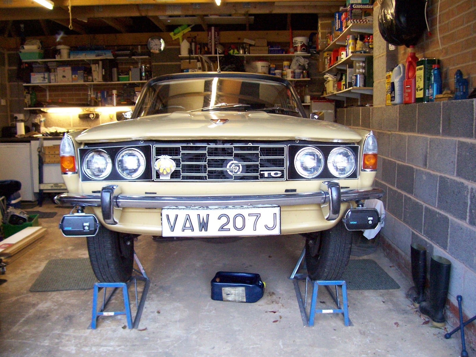
- Put the car up on ramps
First, we followed the Workshop Manual (1967 edition) page 32A, Operation A1-13 “Sump and Internal Oil Filter Remove and Refit”, to gain access to the crankshaft.
Note that when removing the sump, there are two long bolts either side of the crank, at both the front and the rear of the sump, don’t get these mixed up. There are also two bolts fastening the bellhousing to the sump.
With the sump removed, you’re faced with a good view of the crankshaft.
Big End Bearings
By gripping the crankshaft pulley, turn the crankshaft until the number 1 Big End (corresponding to number 1 piston) is at 4 O’clock (Just past Bottom Dead Centre) This will give you room to access the top bearing shell as you’ll see later.
Undo the nuts on the bearing cap and remove. You’ll have a crank like this:
And bearing cap and shell like this:
Slide the bearing shell out from the left hand side – the side without the ‘notch’ or ‘lug’ so that the lug comes out first. Then put the new shell in, in the same way that the old one came out. Plain end first starting on the ‘notch’ side so that the ‘lug’ goes in last and sits in the notch. Smother the new bearing in Graphogen.
Then do that top shell. Push the Big End off the crank, pushing the piston up into the cylinder, and lift over the top of the crank to the other side – that’s why I said set it at 4 O’clock to give you enough room, and repeat the same remove / replace procedure of the shell – and smother it in Graphogen.
Dave and I worked great as a team during this operation. Both of us under the car (I got a great sun tan on my legs that day!!). I’d been told by someone that I mustn’t let go of the Con-Rod or the piston might fall out of the cylinder which would be more than a real pain. Later, another mate told me that they were ‘having me on’ because the piston can’t fall out of the bottom because of the way they’re made. Well, I wasn’t taking any chances. We had our bearings prepared, clean and oily in a box with us under the car. I held on to the Con-Rod, Dave passed me the bearings, took the old bearings off me and put them in a separate box, and squeezed the Graphogen onto my fingers. Proper team work.
We then put both parts of the big end back together. Note that when replacing the Big Ends, the notches/lugs on both upper and lower bearings go together, and on the one side of the Big End cap and the upper part of the Con-Rod both have the number of the cylinder. These numbers also go together, make sure you don’t get these the wrong way round. Replace the nuts and torque up to 30 Lb ft.
Repeat the same process for the other 3 Big Ends.
Main Bearings
If you look at the main bearing caps, they are all numbered and all have an arrow pointing to the front of the engine. They are also sitting on lugs to prevent them being put on the wrong way round.
Because they’re all numbered, I took all 5 Main caps off. I had to use the torque wrench to get them off, they’re very tight. Once unscrewed, they should come off by wiggling them backwards and forwards to get them off the alignment lugs. Main cap number 5 is different to the others, it goes all the way back to the bellhousing and holds the rubber semi-circular sump seal, which I replaced with a new one, and underneath is the rear crank lip seal. This main cap was very stiff and needed repeated tapping with a rubber mallet to free it up.
The next thing to do is to release the tension off the bottom chain tensioner. Unscrew the hex head plug on the end of the tensioner housing and remove with the copper washer. Insert a 1/8 inch Allen key and turn clockwise. You might need to pull on the allen key at the same time to ensure the tensioner is backed off into the housing rather than the allen key get pulled in. I initially forgot to back the tension off mine, and wondered why my bearings were so difficult to remove!
Now, give the crank a little wiggle and you should notice some play, we don’t need much so don’t put a lot of weight behind it!
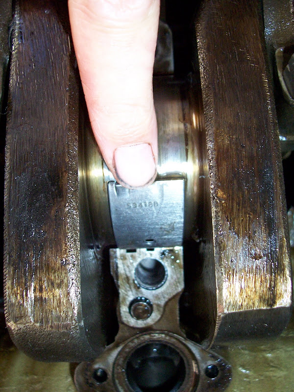
I started from bearing 5 and worked my way forward to number 1. Now this is the point when you use Harvey’s specially crafted tool, the lolly stick. Cut the rounded end off one of them so that we have a nice flat end. Insert the lolly stick on the other side of the bearing to the lug/notch and push/tap the bearing in. When you have about 5mm or so, it's possible to get a grip on the lug with your fingers and pull the bearing all the way round until it is sitting underneath the crank, you can then just lift it off!
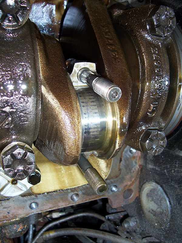
This the old bearing being removed from Main 5 - hence the orange rear crank lip seal.
Next, oil the new bearing (don't use Graphogen on this one or you'll never push it round) and put it on the bottom of the crank with the plain end next to the notch and slide the bearing round the crank until the lug sits in the notch.
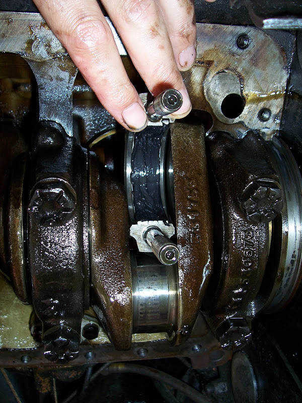
This is a new bearing being slid into the centre bearing - No.3
And repeat this process for all main bearings.
I had trouble with number 1 Main. First I forgot to release the bottom chain tensioner which was preventing the crank from dropping, then it was still stiff, so Harvey suggested we turn the crank by hand (gently because it's the wrong way) to help twist out the bearing. That worked. However, after we got it out, it was obvious why it was stiff. The chain is still pulling on the crank, and pulling it towards the right hand side of the car, so Dave pushed the crank towards the left and the new bearing slipped in nice and easy just like the others.
Replace the bottom bearings in exactly the same way as the Big Ends, smother them in Graphogen and replace them on the engine block. These torque up to 65 Lb ft.
All done!
Now put it all back together.
- Don't forget to replace the Internal Oil Filter 'O' ring gasket with a new one. Any leaks here could mean that your oil pump is sucking air out of the sump instead of oil!
- Don't forget to put the tensioner back onto the lower chain. Turn the Allen key clockwise to release the tensioner. Put the hex head plug/washer back, it’s a bit fiddly and needs to be done by ‘feel’ so take your time.
- Don't forget to replace the rear sump oil seal on main No 5 bearing cap.
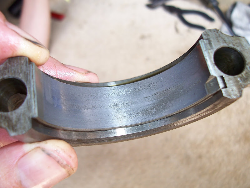
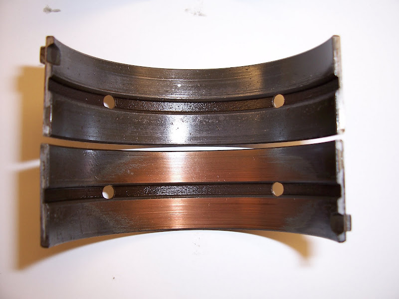
After 65,996 miles, my Big End Bearings were not actually in too bad a state, it looks as though my low oil pressure was a result of wear on my Main bearings. This is one of the worst, this is the old shell bearings from number 2 Main.
The bottom bearing shell has taken most of the wear and down to the copper colour underneath.
It is a relatively straight forward job. Dave and I completed the job in 6-7 hours, and that included a lunch break and lots of prodding 'umm'ing and 'aah'ing and of course lots of Rover talk. We did the job very slowly, very methodically, very carefully, and we’ve done it right. The only areas that held us up were:
- Main bearing cap 5 being tight, but progressive tapping with a rubber mallet freed it.
- Main bearing number 1 being tightly held by the crank. But by releasing the tension off the lower chain, and having someone push the crank to the left will enable the old bearing shell to be pushed over the top of the crank, and the new one inserted.
 Well, it looks like a rusty bit of rubbish here, but its actually very solid.
 Scrubbed up well didn't it! You can see just underneath the push button for the boot where the tow bar bolts onto the rear jacking point. Of course I've taken the rear bumper and valance off to trial fit, because they're in the way to drill the jacking point, and I'm taking the opportunity to respray the valance at the same time.
  The tow bar, even though it was removed from a Rover P6 (I've emailed the seller to ask how it was attached when they removed it - but not holding my breath!) is too short by about 3/8 inch each side. At the moment, I'm using flanged nuts (oversized, nuts are M10, bolt is M8) to act as spacers that I can tighten the two up good and tight. Still not sure how it will fit once the bumper is back on, but that'll have to wait until the weekend when I've finished painting the rear valance.


