My heated rear window has never worked since I've had the car ........ since 1995. There were so many cracks in the heating element that no amount of silver "electric" paint would fix. I don't know why it was like that, but I've a suspicion that my Mum might have given the window a quick scrape on the inside to get rid of the frozen condensation!!! Nooooooo!
Anyway, a chap (Simon Owen) I met on the Rover Forum (best Rover Forum around!) was offering a free heated rear window along with the best part of half a gearbox. He was only 40 minutes drive away so I took up the offer (thanks Simon). The window was green and had been sitting in his back garden for over a year. I cleaned it up, brought the copper elements back to the right colour and connected a battery ......... it all worked, superb.
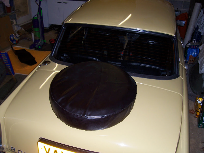
As I had plans to fit a boot mounted spare wheel (another blog entry!) I waited until then to fit it. It is so much easier with the boot lid off.
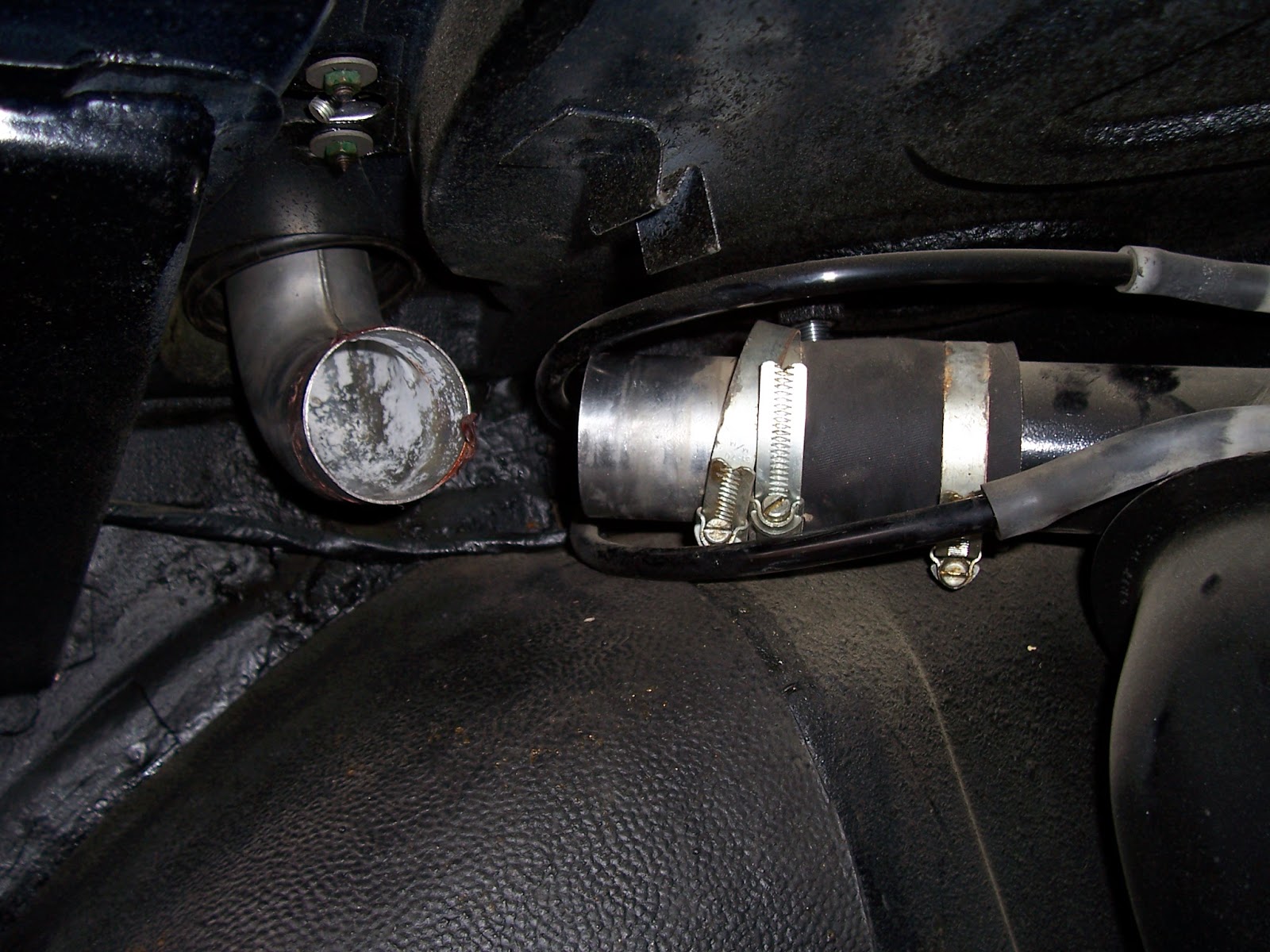 First thing to do is to remove the petrol cap so that we can remove the rear decker panel. By undoing the jubilee clip and wiggling the pipes will dislodge the sealant sticking the pipe to the rubber tube.
Remove the four screws that fasten the petrol cap to the decker panel and pull the petrol cap out.
 Next, to remove the rear decker panel, remove the 3 bolts near the boot hinges - one at either side and one in the middle.
Then underneath the decker panel, on each side there is a nut and washer on a bolt that is attached to the decker panel. you can see it in this photo. remove these nuts/washers.
The decker panel should now lift off, it will be a little stiff and tight but it will wiggle free.

Remove the centre screen support and the nylon spacer underneath.
On each side there is a screen "jack" like this photo. Remove the dum-dum covering the thread and nut and turn the nut to wind the jack down as far as it will go. Do the same for the other side.
There is now nothing left holding the screen in place, except whatever sealant was used when the screen was last fitted.
Open each rear passenger door, remove the seats and inner rear quarter panels and disconnect the heated rear screen wires. With one hand on the inside, and one on the outside of the screen, wiggle and push the screen in a downward movement to try to slide the window out.
You might find it useful to slide a blunt instrument underneath the
rubber seal around the stainless steel trim to free off the sealant
there.
Constant wiggling and pushing from alternate sides will eventually free the screen and rubber from its hold and it will come out.
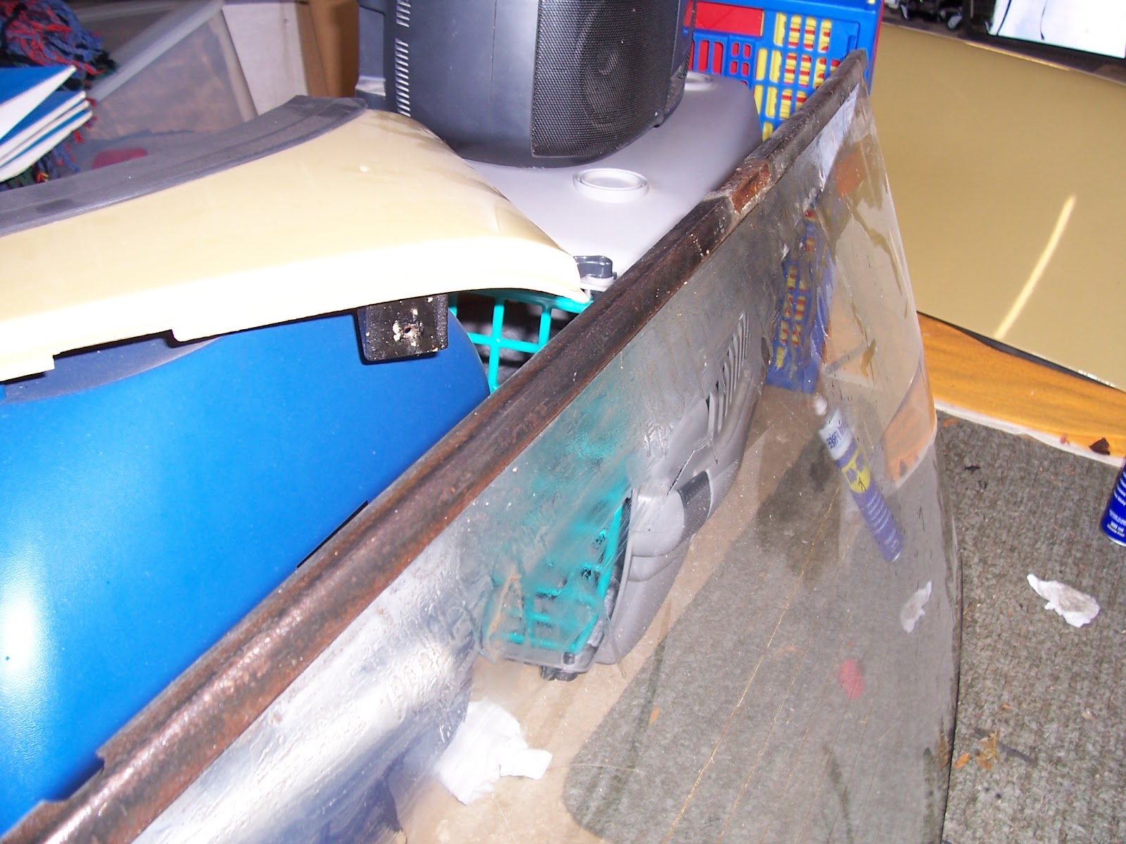
Here is a photo of the old screen upside down. You can see on the bottom, a metal piece of angle, the same shape as the window, this needs to come off along with the rubber underneath so that it can be fitted to the new window. This (after 39 years) took some removing, and I think the rubber was glued to the glass in a spot each side - probably to help the fitters originally building the cars, so that it doesn't fall off when you hold the window the right way up!
Remove it, along with the sealing rubber from the top and sides and clean them up. Apply screen sealant and fit to the replacement window.

Insert the replacement screen by reversing the removal procedure - by sliding the window up into the aperture, make sure that the rubber seal goes inside the aperture with the rubber lip around the stainless steel trim.
Jack up the window gradually on each side to push the window firmly home. Periodically pull the window up into the aperture by hand (one hand inside the car, the other outside) to make sure that the window is being correctly seated and to check how much play is left to be taken up.
Continue to jack up the window until it is fully home. You should be able to see where it was before by the marks left on the stainless steel trim by the rubber seal and you can 'feel' the jack getting tighter. Don't over tighten, otherwise it could crack during use as the car will flex while driving.

Another view.......

Refit the rear decker panel and the petrol cap. Apply a gasket compound around the petrol pipe and connect the rubbers and do up the jubilee clips.
Refit the four screws holding the petrol cap to the decker panel - use a magnetic screwdriver, if you drop on of these down the pipe, it'll end up in your petrol tank!!
All Done!!

Anyway, a chap (Simon Owen) I met on the Rover Forum (best Rover Forum around!) was offering a free heated rear window along with the best part of half a gearbox. He was only 40 minutes drive away so I took up the offer (thanks Simon). The window was green and had been sitting in his back garden for over a year. I cleaned it up, brought the copper elements back to the right colour and connected a battery ......... it all worked, superb.
As I had plans to fit a boot mounted spare wheel (another blog entry!) I waited until then to fit it. It is so much easier with the boot lid off.
First thing to do is to remove the petrol cap so that we can remove the rear decker panel. By undoing the jubilee clip and wiggling the pipes will dislodge the sealant sticking the pipe to the rubber tube.Remove the four screws that fasten the petrol cap to the decker panel and pull the petrol cap out.
Next, to remove the rear decker panel, remove the 3 bolts near the boot hinges - one at either side and one in the middle.Then underneath the decker panel, on each side there is a nut and washer on a bolt that is attached to the decker panel. you can see it in this photo. remove these nuts/washers.
The decker panel should now lift off, it will be a little stiff and tight but it will wiggle free.
Remove the centre screen support and the nylon spacer underneath.
On each side there is a screen "jack" like this photo. Remove the dum-dum covering the thread and nut and turn the nut to wind the jack down as far as it will go. Do the same for the other side.
There is now nothing left holding the screen in place, except whatever sealant was used when the screen was last fitted.
Open each rear passenger door, remove the seats and inner rear quarter panels and disconnect the heated rear screen wires. With one hand on the inside, and one on the outside of the screen, wiggle and push the screen in a downward movement to try to slide the window out.
You might find it useful to slide a blunt instrument underneath the
rubber seal around the stainless steel trim to free off the sealant
there.
Constant wiggling and pushing from alternate sides will eventually free the screen and rubber from its hold and it will come out.
Here is a photo of the old screen upside down. You can see on the bottom, a metal piece of angle, the same shape as the window, this needs to come off along with the rubber underneath so that it can be fitted to the new window. This (after 39 years) took some removing, and I think the rubber was glued to the glass in a spot each side - probably to help the fitters originally building the cars, so that it doesn't fall off when you hold the window the right way up!
Remove it, along with the sealing rubber from the top and sides and clean them up. Apply screen sealant and fit to the replacement window.
Insert the replacement screen by reversing the removal procedure - by sliding the window up into the aperture, make sure that the rubber seal goes inside the aperture with the rubber lip around the stainless steel trim.
Jack up the window gradually on each side to push the window firmly home. Periodically pull the window up into the aperture by hand (one hand inside the car, the other outside) to make sure that the window is being correctly seated and to check how much play is left to be taken up.
Continue to jack up the window until it is fully home. You should be able to see where it was before by the marks left on the stainless steel trim by the rubber seal and you can 'feel' the jack getting tighter. Don't over tighten, otherwise it could crack during use as the car will flex while driving.
Another view.......
Refit the rear decker panel and the petrol cap. Apply a gasket compound around the petrol pipe and connect the rubbers and do up the jubilee clips.
Refit the four screws holding the petrol cap to the decker panel - use a magnetic screwdriver, if you drop on of these down the pipe, it'll end up in your petrol tank!!
All Done!!
 The cross-bar is only made of aluminium and spot welded in place. Drill the spot welds out carefully, there is no need to drill al the way through, the spot welds will break off with a wiggle of the cross-bar.
 Turn the boot lid over and drill a small pilot hole (I used a centre bit) at the mark previously made on the outside. Go carefully, using a centre punch will really only chip away the paint, so a very slow controlled drilling is required. Fortunately, the boot being made of aluminium, slow drilling will easily drill a hole.
 Position the spider brace in position using the scribed circle as a guide. Check for a good fit and because not all boot lids are the same, and the spider brace will likely be second hand, you might find as I did, that the bones of the boot lid might need some persuasion with a hammer and the spider brace bending a little in a vice.
 When satisfied that the spider brace is about as good as you can get it, position sufficient shims between the spider brace and the boot lid to take up all free space and prevent the boot lid from denting when you tighten up the locking plate.

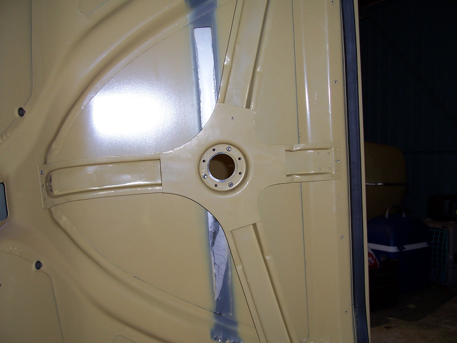 And from underneath.....
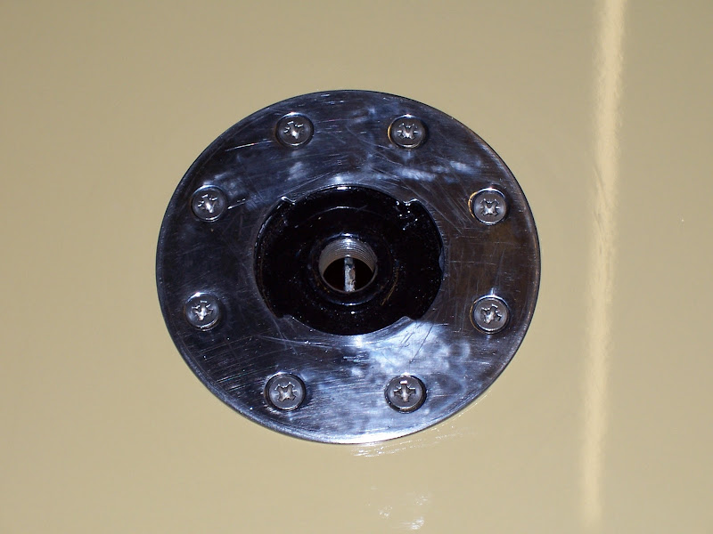 Now, remove the shim fitted to the outside as a guide and fit the locking plate and the stainless steel slotted plate on the outside. screw these up with #10 UNF countersunk screws and nyloc nuts.
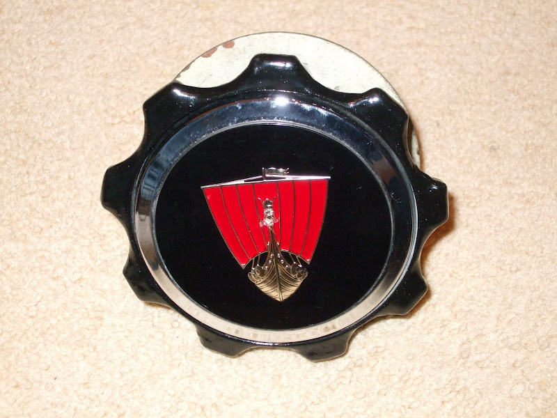
 When finished, the boot mount badge slots into the stainless steel slotted plate and finishes the boot off really well for those times where you want the spare wheel in the boot. Otherwise, the rain would get in the boot!
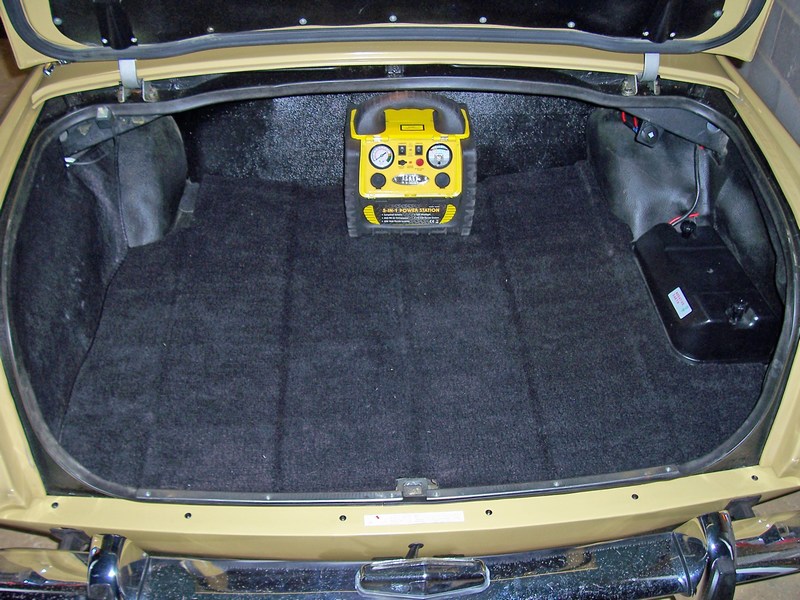
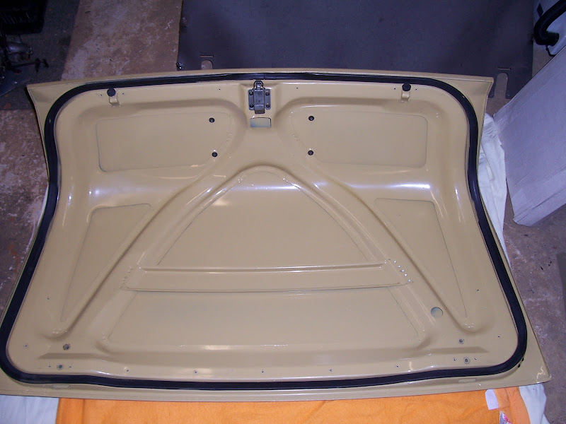
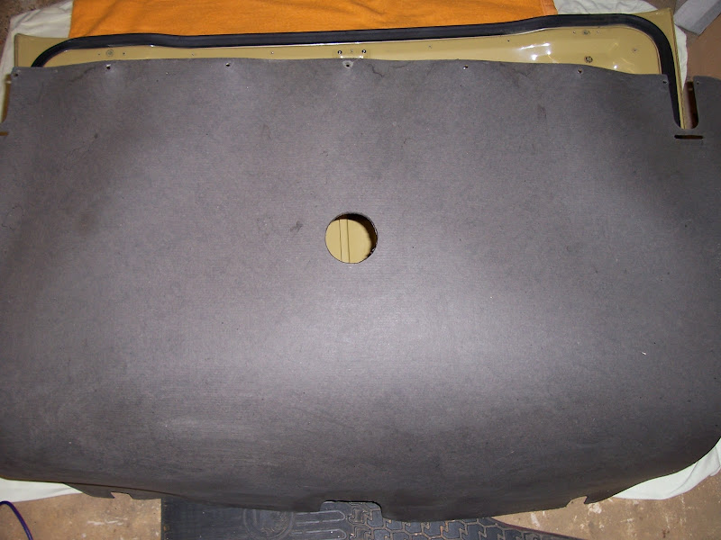 Here is the hardboard boot lid liner with the hole cut that we previously marked out.
 Here with the boot lid liner in place, the locking plate can be accessed to ensure that the spare wheel or the badge cannot be stolen.
 Next, the boot lid handle needs to be fitted. This is all described in the instructions and the measurements fr the holes needs to be made first, and then drilled on the face of the boot lid.
 Here is the boot handle fitted (boot lid upside down).
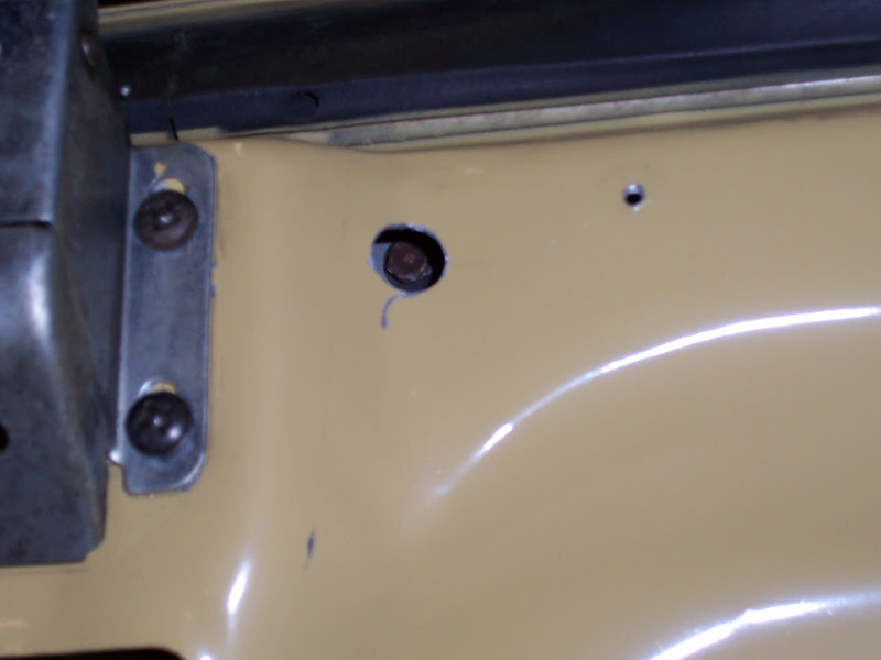 Here is a close up of the boot handle fitting. The large hole capable of accepting a socket, and inside the hole, you can see the head of the bolt that is fastening the boot handle on.
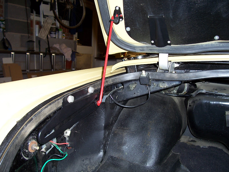 Finally, the boot prop needs to be fitted.