Fitting the Boot Mount Kit
When it comes to fitting one of
these kits, there are those who say it can be done with the boot lid
still on the car, but I found that it was much easier to take the boot
off. Removing the boot on a P6 is very simple, however one thing that
is easier with it on the car is measuring! I didn't, and it would have
been easier if I had. Using a soft pencil, mark the centre line down
the boot, then measure a mark 314mm down from the top edge (nearest the
rear window), this is where we want the centre of the hole!

With the boot lid off and the hardboard removed, you can see the 'A' shape of the bones inside. The cross-bar of the 'A' needs to be removed to enable fitting of the spider brace.
 The cross-bar is only made of aluminium and spot welded in place. Drill the spot welds out carefully, there is no need to drill al the way through, the spot welds will break off with a wiggle of the cross-bar.
 Turn the boot lid over and drill a small pilot hole (I used a centre bit) at the mark previously made on the outside. Go carefully, using a centre punch will really only chip away the paint, so a very slow controlled drilling is required. Fortunately, the boot being made of aluminium, slow drilling will easily drill a hole.
Turn the boot lid over again and using a set of dividers set to the radius of the hole in the spider brace, scribe a circle using the hole as the centre of circle.
 Position the spider brace in position using the scribed circle as a guide. Check for a good fit and because not all boot lids are the same, and the spider brace will likely be second hand, you might find as I did, that the bones of the boot lid might need some persuasion with a hammer and the spider brace bending a little in a vice.
 When satisfied that the spider brace is about as good as you can get it, position sufficient shims between the spider brace and the boot lid to take up all free space and prevent the boot lid from denting when you tighten up the locking plate.
Hold the spider brace in place and mark the position of the first rivet. Drill a 5mm hole, then reposition the brace. If the drilled hole is not quite right, elongate the hole until correct, then insert a 5mm pop rivet.
On the opposite arm, drill the next hole and pop rivet. Now the spider brace is in it's final position.
Careful drilling these holes, it is easy to put too much pressure on the drill and when it goes through the 'bones' of the boot lid marking the inside of the outer skin causing a dent.

Next drill all eight of the holes around the large hole of the spider brace using the spider brace as the guide. After cleaning up the holes on the outside of the boot lid, position a spare shim on the outside and using a few screws tighten up spider brace. This will keep the brace nice and tight while the large hole is drilled and also preventing the drill slipping and marking the perfect boot lid!

I used a hole saw for this. The hole saw is really meant for wood, but I figured that it would make small work of an aluminium boot lid. It soon went through it. It made a bit of a poor finish, but the burrs were on the inside. My rotary tool made light work of cleaning up the burrs and making a perfect hole
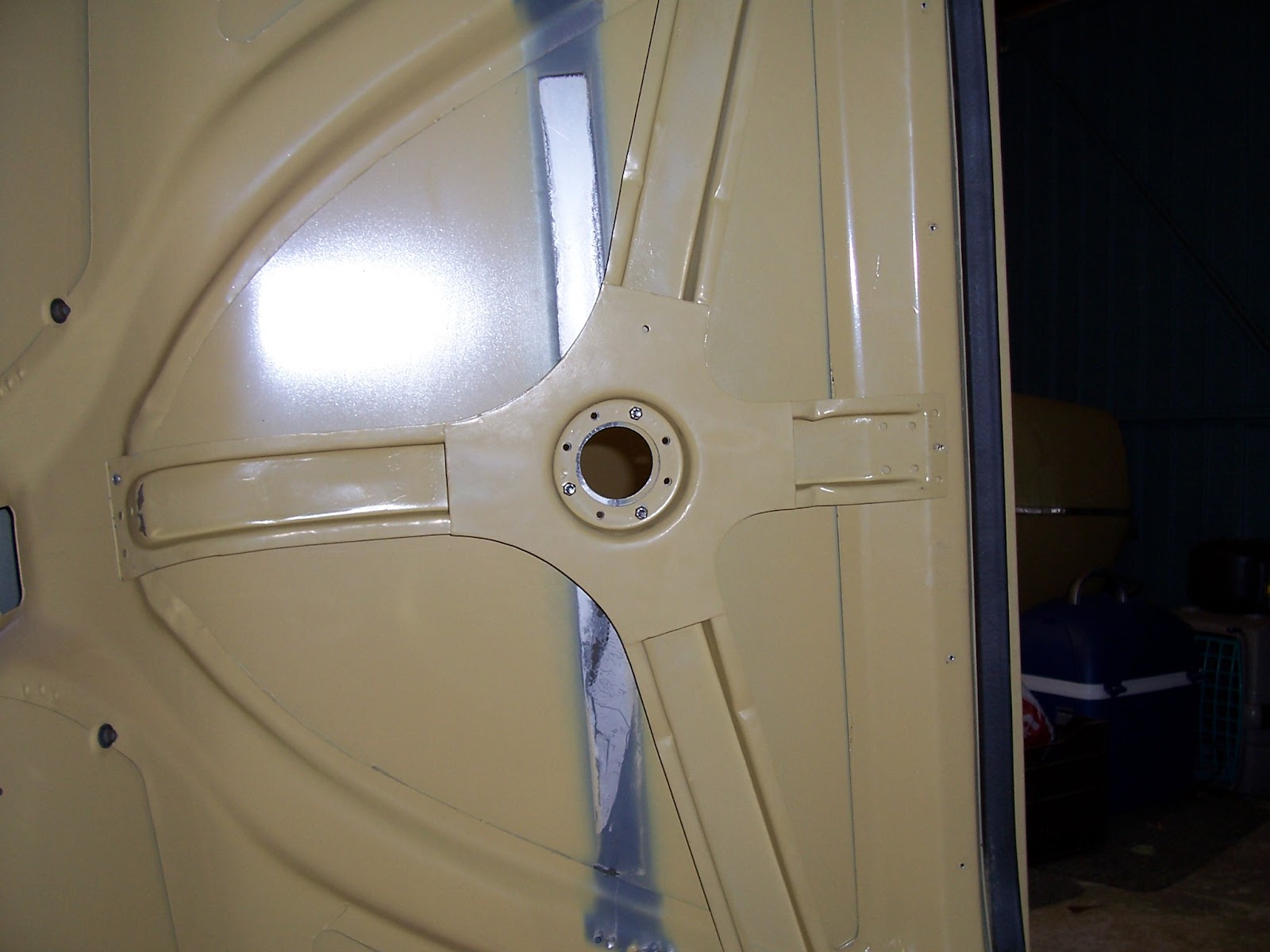 And from underneath.....
At this point it is well worth re-fitting the hardboard cover to the inside of the boot lid. Then with a pencil, draw through the hole and trace the outline of the circle. This will enable you to operate the locking plate when fitted.
 Now, remove the shim fitted to the outside as a guide and fit the locking plate and the stainless steel slotted plate on the outside. screw these up with #10 UNF countersunk screws and nyloc nuts.
That's the middle bit finished, and it holds the spider brace nicely in place too.
To finish off, drill and pop rivet the remaining holes in the spider brace one by one so that it is held firmly.
 When finished, the boot mount badge slots into the stainless steel slotted plate and finishes the boot off really well for those times where you want the spare wheel in the boot. Otherwise, the rain would get in the boot!
 Here is the hardboard boot lid liner with the hole cut that we previously marked out.
Cut this with a stanley knife, do it gradually and eventually it will cut all the way through. Don't try to cut all the way through in one go otherwise there is a tendency to apply too much pressure and cut too much.
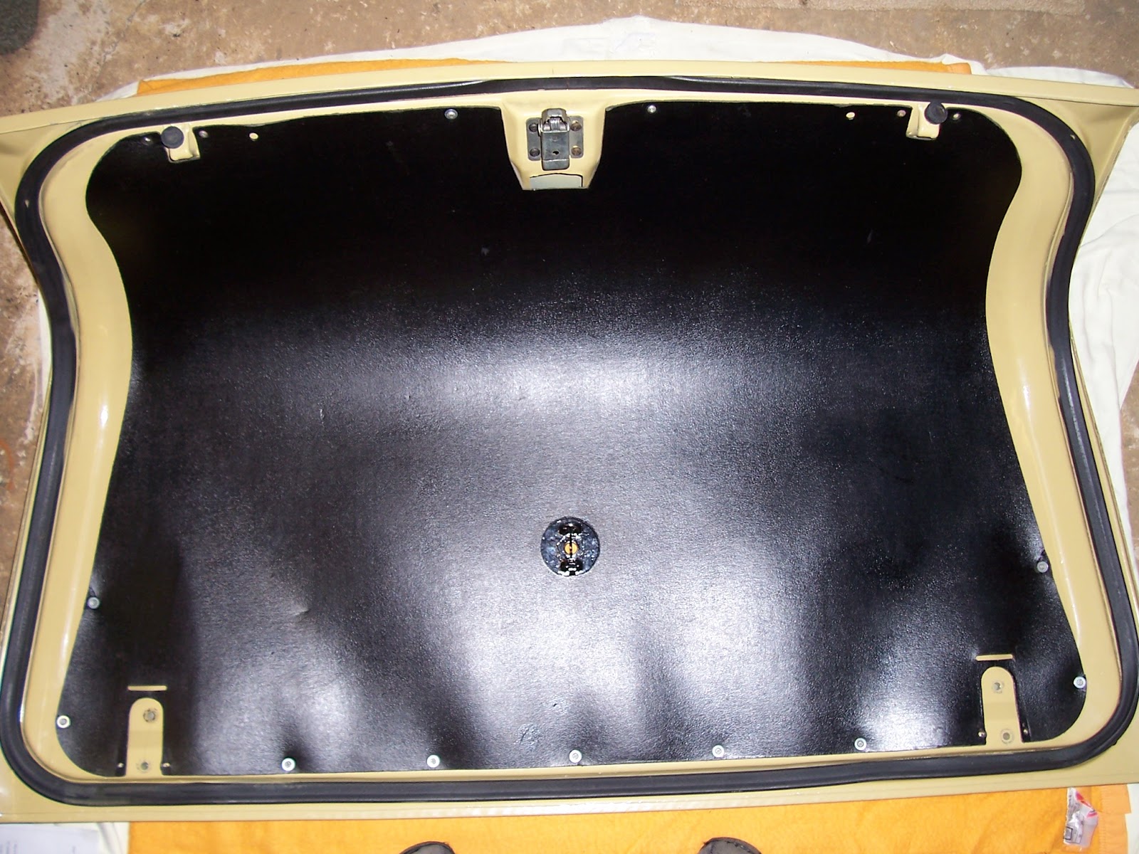 Here with the boot lid liner in place, the locking plate can be accessed to ensure that the spare wheel or the badge cannot be stolen.
 Next, the boot lid handle needs to be fitted. This is all described in the instructions and the measurements fr the holes needs to be made first, and then drilled on the face of the boot lid.
To be able to fit the handle, we need to make two large holes on the inside of the boot lid either side fo the lock. These holes need to be large enough to get a socket through to offer the bolts through the outer holes.
To avoid losing the bolt, put blu-tak in the socket, and put the head of the bolt into the blu-tak, then feed it through the large outer hole and through the small drilled hole and screw into the handle.
 Here is the boot handle fitted (boot lid upside down).
Note that the boot handle is actually a P6 Series 1 door handle fitted upside down!
 Here is a close up of the boot handle fitting. The large hole capable of accepting a socket, and inside the hole, you can see the head of the bolt that is fastening the boot handle on.
 Finally, the boot prop needs to be fitted.
The best way to find the right place to fit both the bracket on the base unit, and the bracket on the boot lid, is to make a template. Using the measurements in the instructions, make a paper template. The boot lid bracket is positioned in relation to the hinge bolts, the base unit bracket is positioned in relation to the bolt attaching the rear top-link of the suspension - in the bottom left hand corner of the photo.
Correct positioning of these brackets enable the red prop rod to slide up and down the bracket as you open and close the lid.
The prop ensures that the spare wheel does not come into contact with the rear screen, and also locks the boot lid in the open position to prevent it landing on your head!

All finished.......... nearly

I only found this out when I'd finished. When I re-fitted the boot lid to the hinges, I let the boot lid 'hang' or flop against the hinges. As a result, it temporarily put stress on the outer skin cracking/chipping the paint.
When you put your boot lid back on the car, put it on with someone else to lend a hand, and keep them helping while you do the bolts up!
Now, I've got to wait until the warmer weather to sand it back and respray it :-(

When it comes to fitting one of
these kits, there are those who say it can be done with the boot lid
still on the car, but I found that it was much easier to take the boot
off. Removing the boot on a P6 is very simple, however one thing that
is easier with it on the car is measuring! I didn't, and it would have
been easier if I had. Using a soft pencil, mark the centre line down
the boot, then measure a mark 314mm down from the top edge (nearest the
rear window), this is where we want the centre of the hole!
With the boot lid off and the hardboard removed, you can see the 'A' shape of the bones inside. The cross-bar of the 'A' needs to be removed to enable fitting of the spider brace.
The cross-bar is only made of aluminium and spot welded in place. Drill the spot welds out carefully, there is no need to drill al the way through, the spot welds will break off with a wiggle of the cross-bar.Turn the boot lid over and drill a small pilot hole (I used a centre bit) at the mark previously made on the outside. Go carefully, using a centre punch will really only chip away the paint, so a very slow controlled drilling is required. Fortunately, the boot being made of aluminium, slow drilling will easily drill a hole.Turn the boot lid over again and using a set of dividers set to the radius of the hole in the spider brace, scribe a circle using the hole as the centre of circle.
Position the spider brace in position using the scribed circle as a guide. Check for a good fit and because not all boot lids are the same, and the spider brace will likely be second hand, you might find as I did, that the bones of the boot lid might need some persuasion with a hammer and the spider brace bending a little in a vice.When satisfied that the spider brace is about as good as you can get it, position sufficient shims between the spider brace and the boot lid to take up all free space and prevent the boot lid from denting when you tighten up the locking plate.Hold the spider brace in place and mark the position of the first rivet. Drill a 5mm hole, then reposition the brace. If the drilled hole is not quite right, elongate the hole until correct, then insert a 5mm pop rivet.
On the opposite arm, drill the next hole and pop rivet. Now the spider brace is in it's final position.
Careful drilling these holes, it is easy to put too much pressure on the drill and when it goes through the 'bones' of the boot lid marking the inside of the outer skin causing a dent.
Next drill all eight of the holes around the large hole of the spider brace using the spider brace as the guide. After cleaning up the holes on the outside of the boot lid, position a spare shim on the outside and using a few screws tighten up spider brace. This will keep the brace nice and tight while the large hole is drilled and also preventing the drill slipping and marking the perfect boot lid!
I used a hole saw for this. The hole saw is really meant for wood, but I figured that it would make small work of an aluminium boot lid. It soon went through it. It made a bit of a poor finish, but the burrs were on the inside. My rotary tool made light work of cleaning up the burrs and making a perfect hole
And from underneath.....At this point it is well worth re-fitting the hardboard cover to the inside of the boot lid. Then with a pencil, draw through the hole and trace the outline of the circle. This will enable you to operate the locking plate when fitted.
Now, remove the shim fitted to the outside as a guide and fit the locking plate and the stainless steel slotted plate on the outside. screw these up with #10 UNF countersunk screws and nyloc nuts.That's the middle bit finished, and it holds the spider brace nicely in place too.
To finish off, drill and pop rivet the remaining holes in the spider brace one by one so that it is held firmly.
When finished, the boot mount badge slots into the stainless steel slotted plate and finishes the boot off really well for those times where you want the spare wheel in the boot. Otherwise, the rain would get in the boot!Here is the hardboard boot lid liner with the hole cut that we previously marked out.Cut this with a stanley knife, do it gradually and eventually it will cut all the way through. Don't try to cut all the way through in one go otherwise there is a tendency to apply too much pressure and cut too much.
Here with the boot lid liner in place, the locking plate can be accessed to ensure that the spare wheel or the badge cannot be stolen.Next, the boot lid handle needs to be fitted. This is all described in the instructions and the measurements fr the holes needs to be made first, and then drilled on the face of the boot lid.To be able to fit the handle, we need to make two large holes on the inside of the boot lid either side fo the lock. These holes need to be large enough to get a socket through to offer the bolts through the outer holes.
To avoid losing the bolt, put blu-tak in the socket, and put the head of the bolt into the blu-tak, then feed it through the large outer hole and through the small drilled hole and screw into the handle.
Here is the boot handle fitted (boot lid upside down).Note that the boot handle is actually a P6 Series 1 door handle fitted upside down!
Here is a close up of the boot handle fitting. The large hole capable of accepting a socket, and inside the hole, you can see the head of the bolt that is fastening the boot handle on.Finally, the boot prop needs to be fitted.The best way to find the right place to fit both the bracket on the base unit, and the bracket on the boot lid, is to make a template. Using the measurements in the instructions, make a paper template. The boot lid bracket is positioned in relation to the hinge bolts, the base unit bracket is positioned in relation to the bolt attaching the rear top-link of the suspension - in the bottom left hand corner of the photo.
Correct positioning of these brackets enable the red prop rod to slide up and down the bracket as you open and close the lid.
The prop ensures that the spare wheel does not come into contact with the rear screen, and also locks the boot lid in the open position to prevent it landing on your head!
All finished.......... nearly
I only found this out when I'd finished. When I re-fitted the boot lid to the hinges, I let the boot lid 'hang' or flop against the hinges. As a result, it temporarily put stress on the outer skin cracking/chipping the paint.
When you put your boot lid back on the car, put it on with someone else to lend a hand, and keep them helping while you do the bolts up!
Now, I've got to wait until the warmer weather to sand it back and respray it :-(
2 comments:
MOHEGAN CASINO, HOSPITALITY & SITE - JT Hub
MOHEGAN CASINO, HOSPITALITY & SITE - JT Hub. 성남 출장샵 3131 제천 출장안마 S. 파주 출장샵 Atlantic City, 목포 출장샵 NJ 08401 - view map. http://www.jtmhub.com/index.php?hot_table=6f2f3w2 안성 출장안마
Fitting the boot mount kit to the Rover P6, as explained by Brian Humphreys, improves both functionality and style. For professional help with Car Shock Absorber Repair, check out their services.
Post a Comment